(Hong Kong)

Product Summary
Digital supply voltage.
Ground.
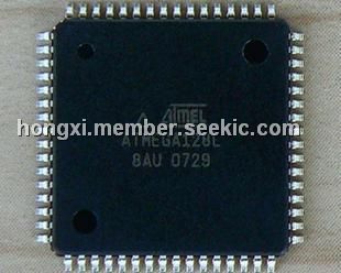
ATMEGA128L-8AU ATMEGA128L-8AI
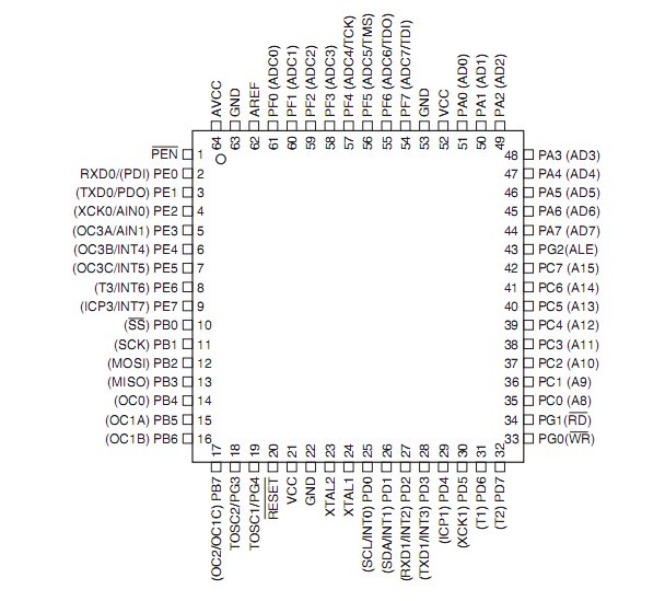
Port A is an 8-bit bi-directional I/O port with internal pull-up resistors (selected for each
bit). The Port A output buffers have symmetrical drive characteristics with both high sink
and source capability. As inputs, Port A pins that are externally pulled low will source
current if the pull-up resistors are activated. The Port A pins are tri-stated when a reset
condition becomes active, even if the clock is not running.
Port A also serves the functions of various special features of the ATmega128 as listed
on page 72.
Port B is an 8-bit bi-directional I/O port with internal pull-up resistors (selected for each
bit). The Port B output buffers have symmetrical drive characteristics with both high sink
and source capability. As inputs, Port B pins that are externally pulled low will source
Digital supply voltage.
Ground.ATMEGA128L-8AU ATMEGA128L-8AI
Port A is an 8-bit bi-directional I/O port with internal pull-up resistors (selected for each
bit). The Port A output buffers have symmetrical drive characteristics with both high sink
and source capability. As inputs, Port A pins that are externally pulled low will source
current if the pull-up resistors are activated. The Port A pins are tri-stated when a reset
condition becomes active, even if the clock is not running.
Port A also serves the functions of various special features of the ATmega128 as listed
on page 72.ATMEGA128L-8AU ATMEGA128L-8AI
Port B is an 8-bit bi-directional I/O port with internal pull-up resistors (selected for each
bit). The Port B output buffers have symmetrical drive characteristics with both high sink
and source capability. As inputs, Port B pins that are externally pulled low will source
Parametrics
Mnemonics Operands Description Operation Flags #Clocks
SEV Set Twos Complement Overflow. V ←1 V 1
CLV Clear Twos Complement Overflow V ← 0 V 1
SET Set T in SREG T ← 1 T 1
CLT Clear T in SREG T ← 0 T 1
SEH Set Half Carry Flag in SREG H ← 1 H 1
CLH Clear Half Carry Flag in SREG H ← 0 H 1
Features
1.High-performance, Low-power AVR? 8-bit Microcontroller
2.Advanced RISC Architecture
–133 Powerful Instructions – Most Single Clock Cycle Execution
–32 x 8 General Purpose Working Registers + Peripheral Control Registers
–Fully Static Operation
–Up to 16 MIPS Throughput at 16 MHz
–On-chip 2-cycle Multiplier
3.Nonvolatile Program and Data Memories
–128K Bytes of In-System Reprogrammable Flash
Endurance: 10,000 Write/Erase Cycles
–Optional Boot Code Section with Independent Lock Bits
In-System Programming by On-chip Boot Program
True Read-While-Write Operation
–4K Bytes EEPROM
Endurance: 100,000 Write/Erase Cycles
–4K Bytes Internal SRAM
–Up to 64K Bytes Optional External Memory Space
–Programming Lock for Software Security
–SPI Interface for In-System Programming
4.JTAG (IEEE std. 1149.1 Compliant) Interface
–Boundary-scan Capabilities According to the JTAG Standard
–Extensive On-chip Debug Support
–Programming of Flash, EEPROM, Fuses and Lock Bits through the JTAG Interface
5.Peripheral Features
–Two 8-bit Timer/Counters with Separate Prescalers and Compare Modes
–Two Expanded 16-bit Timer/Counters with Separate Prescaler, Compare Mode and
Capture Mode
–Real Time Counter with Separate Oscillator
–Two 8-bit PWM Channels
–6 PWM Channels with Programmable Resolution from 2 to 16 Bits
–Output Compare Modulator
–8-channel, 10-bit ADC
8 Single-ended Channels
7 Differential Channels
2 Differential Channels with Programmable Gain at 1x, 10x, or 200x
–Byte-oriented Two-wire Serial Interface
–Dual Programmable Serial USARTs
–Master/Slave SPI Serial Interface
–Programmable Watchdog Timer with On-chip Oscillator
–On-chip Analog Comparator
6.Special Microcontroller Features
–Power-on Reset and Programmable Brown-out Detection
–Internal Calibrated RC Oscillator
–External and Internal Interrupt Sources
–Six Sleep Modes: Idle, ADC Noise Reduction, Power-save, Power-down, Standby,
and Extended Standby
–Software Selectable Clock Frequency
–ATmega103 Compatibility Mode Selected by a Fuse
–Global Pull-up Disable
7.I/O and Packages
–53 Programmable I/O Lines
–64-lead TQFP and 64-pad QFN/MLF
8.Operating Voltages
–2.7 - 5.5V for ATmega128L
–4.5 - 5.5V for ATmega128
9.Speed Grades
–0 - 8 MHz for ATmega128L
–0 - 16 MHz for ATmega128
Diagrams
| Image | Part No | Mfg | Description |  |
Pricing (USD) |
Quantity | ||||||||||||
|---|---|---|---|---|---|---|---|---|---|---|---|---|---|---|---|---|---|---|
 |
 ATmega128L-8AU |
Atmel |
8-bit Microcontrollers (MCU) 128kB Flash 4kB EEPROM 53 I/O Pins |
Data Sheet |
|
|
||||||||||||
 |
ATMEGA128L-8AUR |
Atmel |
8-bit Microcontrollers (MCU) AVR,128KB FLASH,8MHZ 4KB EE 4KB SRAM |
Data Sheet |
|
|
||||||||||||